Introduction
Mobile line voltage generators primarily provide alternating current (AC) power at an emergency response event. This may be carried on the fire apparatus and removed during use, or it may be permanently mounted. In some cases, the generator can provide power while driving as well. Typical uses for the AC power include:
• Scene Lighting
• In-Cab Outlets
• Portable Exhaust Fans
• Extrication Equipment
• Power Tools
• Pumps
• Tiller cab HVAC
As a point of clarity, a generator is a machine that changes mechanical energy into electrical energy, either alternating current (AC) or direct current (DC). An alternator is a machine that converts the mechanical energy into AC electrical power. While a line voltage power source could technically be referred to as either a generator or an alternator, we will use the term generator in this paper to mean a device that produces AC line voltage power.
This document will provide methods of sizing a generator for a fire apparatus and then describe the types of devices that may be employed.

Contents
Sizing a Generator for an Apparatus
When sizing a line voltage generator for an Emergency Vehicle (EV) it is important to account for existing equipment power needs, as well as future equipment additions that might increase power requirements during the life of the apparatus. A good rule of thumb is to select a line voltage generator that provides 15%-20% more power than is currently required.
RESISTIVE VS INDUCTIVE LOADS
The first thing to consider when sizing a generator is to distinguish between the two types of devices that will be powered by the generator.
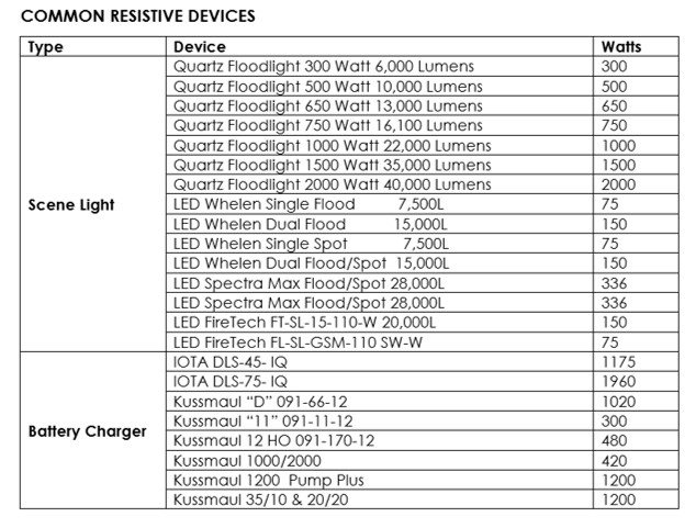
A resistive load device is one whose continuous load and surge load are the same. This is a device that does not draw extra power during start-up. Typical resistive devices on a fire apparatus are lights, communication equipment, and chargers.
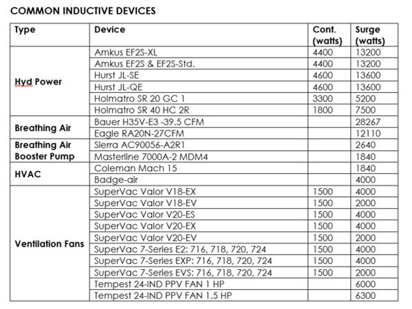
An inductive load device is anything with an electric motor. These include ventilation fans, extrication tools, refrigerators, compressors, as well as microwave ovens. Inductive devices require a “surge” of power during start-up, and this power surge must be accounted for when sizing the generator to avoid overloading the circuit and tripping breakers when the device is started.
SELECTING A SIZING METHOD
There are two approaches to sizing a generator. The Known Devices method is preferred, and should be used if you have a pretty good idea of all the line-voltage devices you will be using at the same time during a response. The Known Circuits method can be used if you are planning a certain number of outlets and cord reels, but you are not in control of what they will be used for. This second method may come into play if you are specifying a general apparatus that could end up in any station and the devices to be powered by the generator all at one time is unknown.
FIXED DEVICES
No matter which generator sizing method you select, the first task is to calculate the load from the devices that are fixed on the apparatus:
- List each of the line-voltage devices that are wired directly to the apparatus.
- Determine the maximum power that each will consume while in operation. This will come from labels on each device, or the device specifications. See Appendix A for values for common devices.
- Convert all the power values into Kilowatts (kW). For inductive load devices, use the starting power or surge power, not the continuous power for your calculations. If you don’t have the wattage of the device directly you can calculate power if you know the voltage and the current the device will draw:
Volts x Amps = Watts
1 kW=1000 watts.
KNOWN DEVICES METHOD
With the Known Devices method, you will be determining the capacity of the generator needed to power all the devices you have identified that will be powered at the same time.
- Add to your list of fixed devices all of the devices that you will be plugging into an outlet or a cord reel at the scene. Again, be sure to use the surge value of power for any inductive device.
- Add up all the power from all the devices on your list.
- Multiply this value by 1.2. This will give you the size of the generator you should consider with a safety factor of 20%.
KNOWN CIRCUITS METHOD
The Known Circuits method requires you to make assumptions about how often each plug or cord reel on the apparatus will be in use at the same time. Make your own assumptions based on your knowledge of the use you believe the apparatus will see.
- Determine the rating of each circuit that feeds cord reels or outlets provided on the apparatus (do not include the circuits for the fixed devices as you have already accounted for them).
- For each outlet circuit, multiply the power rating by 0.25, which will account for 25% of the rating.
- For each cord reel circuit, multiply the power rating by 0.50, which will account for 50% of the rating.
Note: These modification factors are fire industry guidelines using the assumption that not every outlet or cord reel will be used to its circuits capacity. The assumption is that cord reels are going to supply ventilation fans and are more likely to be used at a fire scene than outlets.
- Add the resulting modified power values to the total of the fixed devices power determined earlier.
- Multiply the total value by 1.2. This will give you the size of the generator you should consider with a safety factor of 20%.
Types of Generators
Mobile line voltage generators can be powered in one of three methods:
- Hydraulic drive system where the hydraulic pump is mounted to the diesel engine or transmission power take-off (PTO)
- Direct drive system where a shaft drives the generator directly from an engine or transmission PTO
- Self-contained internal combustion engines driven system, either gas, diesel, liquified petroleum (LG), or compressed natural gas (CNG)
Mobile line voltage generators are available in a broad range of output capacities, typically rated by kilowatt (kW). They can be configured in various voltages levels, phasing, and frequencies.
This discussion will provide an overview of each of the different mobile line voltage generation systems and suggestions on which type of generator is best for each application.
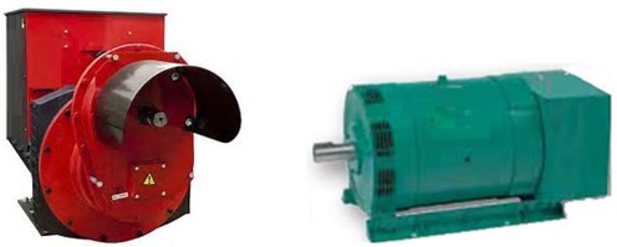
HYDRAULIC DRIVE LINE VOLTAGE GENERATORS
Hydraulic Drive Line Voltage Generators are available in an output capability from approximately 3.0 kW to 40 kW. This style of generator is the most popular system used today in emergency apparatus. It offers flexibility in installation so that the generator can be installed in a wide range of locations, from body compartments to dunnage areas, allowing maximum flexibility for tool and equipment storage.
Hydraulic Drive Generators operate via a hydraulic pump mounted directly or indirectly to a chassis transmission PTO. This pump provides hydraulic oil flow to a hydraulic motor coupled to an alternator. The motor turns the alternator at a constant speed to provide the required voltage and frequency.
The apparatus manufacturer will specify a PTO with a ratio that will provide adequate speed to the hydraulic pump, so that it can provide sufficient hydraulic oil flow at any engine speed. Because of the design configuration of this type of generator, the main apparatus engine must be running to generate AC power.
Hydraulic driven line voltage generators are normally capable of supplying full power during all engine speeds or operation modes. They can typically be turned on or off, whenever the apparatus engine is running. However, caution must be used to engage the PTO only when the apparatus engine speed is below the PTO manufacturer’s recommended max speed limit, which is typically 1000 rpm. In addition, good practices recommend that all loads be removed from any generator before it is turned on or off.
A Hydraulic Drive Generator system normally includes a fluid reservoir which may be located in the generator set housing. However remote installation of the reservoir can be accommodated if installation dictates positioning the reservoir for easier maintenance.
DIRECT DRIVE/PTO POWERED GENERATORS
Direct Drive/PTO Powered Generators are available in an output capability from approximately 15 kW to 50 kW, with various voltage outputs and frequency options. This style of mobile generator obtains its power via a PTO mounted on the apparatus transmission. The PTO drives a shaft connecting the PTO directly to the generator.
Since the direct drive generator spins at a speed in proportion to the speed of the chassis engine, the chassis engine must be governed to a constant speed during operation. This speed is set based on the desired AC frequency (50 hz for Europe, or 60 hz for North America). A direct drive generator can therefore not be operating while the apparatus is driving or pumping. This makes it unsuitable for a pumper or aerial apparatus as the variation in chassis engine speed whilst pumping or positioning the aerial device would not meet the specification of constant/fixed speed. This type of generator is typically used in a Rescue or Command Center application.
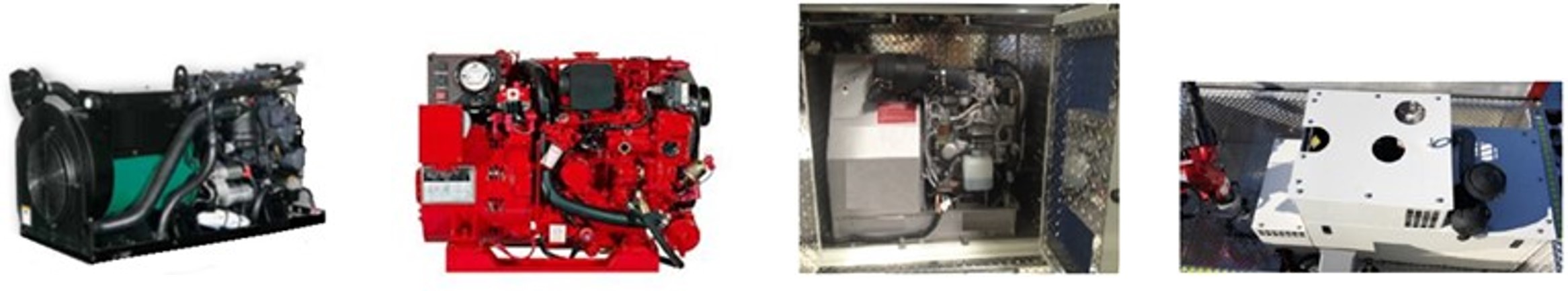
DIESEL ENGINE POWERED GENERATORS
Diesel Engine Powered Generators were the standard type of mobile generator used until about 2006 when hydraulic generators gained popularity. Diesel engine powered mobile generators are available in output capability from approximately 5 kW up to 40 kW. These generator sets provide power independent of the main chassis engine. Where noise levels are a concern, diesel generators are available with ‘quiet packaging’ options that limit noise from the generator to be below 70 dB(A). Diesel generators are typically 40%-50% larger and heavier than a Hydraulic Drive Generator due to the addition of the engine. New efficiencies in Tier 4 engines have provided lower fuel consumptions and lower NOx emissions than previously.
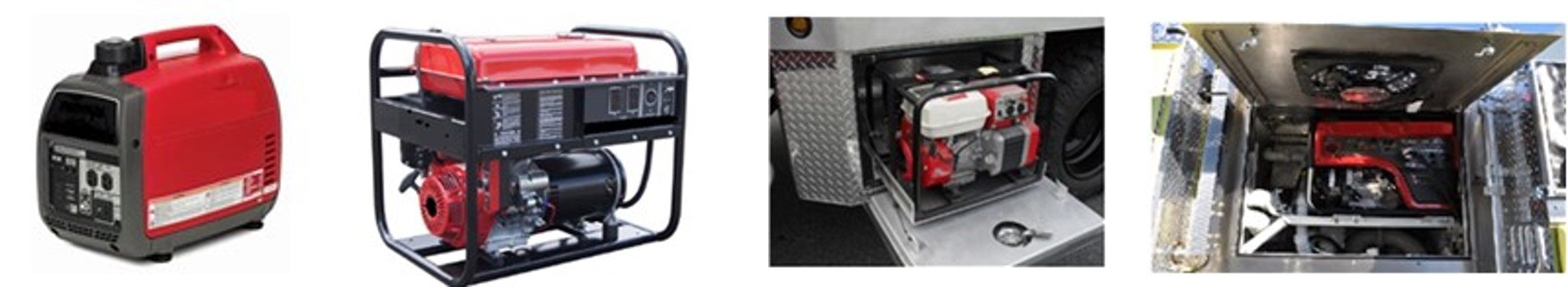
GASOLINE ENGINE POWERED GENERATORS
Gasoline engine powered generators provide from 2.8 kW up to 7.0 kW, 120/240 VAC line power. Like the diesel-powered generators, this design of mobile generator has its own dedicated internal combustion engine for a prime motor. When installed, these generators also provide a fuel efficient and quiet alternative for on-site AC power if the vehicle’s engine is not required to be running. These devices are more often carried in a compartment and removed from the apparatus during use.
OTHER FUEL SOURCES
Mobile generators may be powered by fuels such as Liquified Petroleum (LP) or Compressed Natural Gas (CNG). While these devices are commercially available, they are not really suitable for fire apparatus applications since they would require a separate tank for fuel storage.
IDLE REDUCTION TECHNOLOGY - DIESEL FUEL OR LITHIUM BATTERY POWERED
Idle Reduction Technology (IRT) is common on over-the-road trucks and has been adapted for use in the fire service. IRT diesel systems provide extended on-scene power with the main chassis engine shut down. Several configurations of IRT power packages are available from apparatus manufacturers. The present capabilities of these systems can provide AC and DC power to the vehicle when the chassis engine is shut down. They range in capacity from 7kW to 10kW of AC Power on the diesel IRT systems, to a capacity of 3.3 kWh to 12 kWh on the Lithium battery systems.
This technology is growing in popularity, due to increased efforts in reducing carbon footprint, and reducing the cost of ownership of an emergency apparatus. Fuel efficiencies, providing longer run times, is another driver for this type of mobile generator as well as limiting regeneration occurrences of the main chassis engine after-treatment system.
Summary
This Buyer’s Guide provides an overview of the various types of line voltage generator systems in the emergency apparatus industry, and the recommended use of each. There is a considerable selection of commercially available options for most of these designs, and the apparatus manufacturers can suggest what systems and options can provide reliable, dependable line voltage power for each specific application or mission.
Appendix A – Common Device Power Consumption