Introduction
This guide is intended to provide fire service personnel with information surrounding various fire pump Priming Systems, control considerations and priming pump designs that are commonly used in fire apparatus today. As with any engineered system design, there are advantages and disadvantages to each configuration, design and manufacturer – not all are presented in this document. It is the responsibility of the purchaser to determine what best meets their requirements and to specify this information to prospective apparatus bidders, sellers, and manufacturers.
This guide is presented as a general informative and educational piece, as technology is continuously evolving. The various options and auxiliary equipment presented may not be available from every manufacturer, and some may be mutually exclusive. For more resources, contact the FAMA Member manufacturers listed at www.fama.org.
The National Fire Protection Association (NFPA) Standards define voluntary minimum standards for automotive fire apparatus and water additives. The following are widely used and applicable to priming system requirements and testing:
- NFPA 1900 Standard for Aircraft Rescue and Firefighting Vehicles, Automotive Fire Apparatus, Wildland Fire Apparatus, and Automotive Ambulances.
- NFPA 1910 Standard for the Inspection, Maintenance, Refurbishment, Testing, and Retirement of In-Service Emergency Vehicles and Marine Firefighting Vessels.
It is recommended to reference current NFPA edition when specifying new apparatus. www.nfpa.org

Contents
History:
The first vehicle mounted fire pumps were “Positive Displacement” pumps which meant they were truly “self-priming”. The positive displacement fire pumps initially utilized were typically piston pumps or rotary pumps. A positive displacement pump has the ability to pump both air and water, so all that must be done is to attach a suction line to a water source, engage the pump, open a discharge, and wait for the all the air to move through the pump and the water to follow. This was the earliest, least complicated, and most reliable way to apply a fire stream when operating from a non-pressurized water source.
By the end of World War II, the centrifugal pump dominated the fire service. But centrifugal fire pumps are not self-priming and must have their suction completely flooded with water in order to produce pressure. So, when operating from draft they must have a separate PRIMING SYSTEM to completely flood the suction of the fire pump.
Priming Theory
Priming is the process of replacing the air in the suction hoses and the pump suction cavity with water when operating from draft. This is accomplished by pulling a partial vacuum on the pump and suction hoses allowing the now higher atmospheric pressure to push the water into the pump through the hoses. If the pump is to be operated from draft, priming must be done by means of a small positive displacement pump, or some other device for creating a partial vacuum.
When pumping from a water tank, priming will be accomplished more quickly and positively if the priming system is used.
When operating from hydrants or in a relay, priming is typically not necessary. This is because the inlet water pressure will force the air out of the pump and intake lines, if a pump discharge line is opened to allow the air to escape first.
Priming Pumps
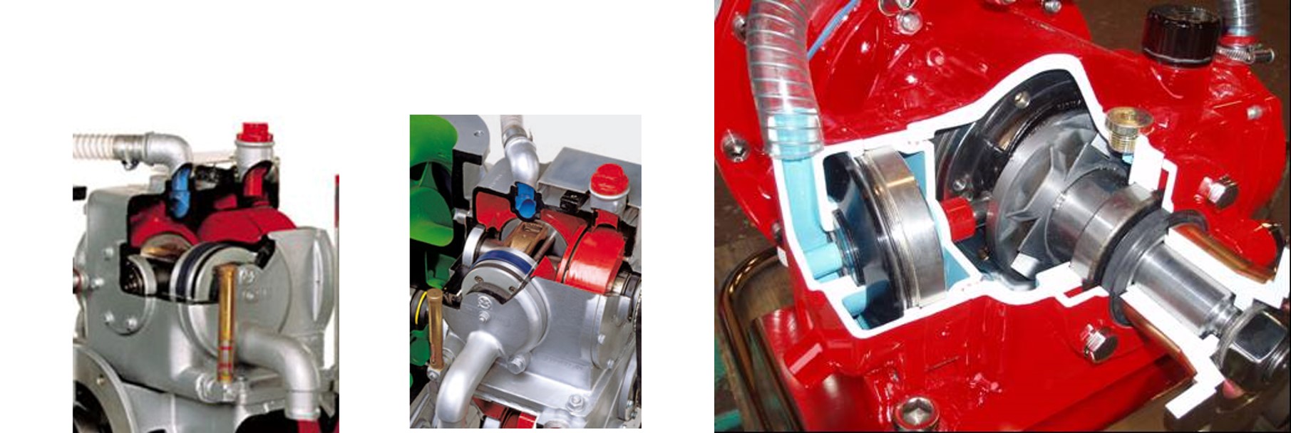
There are three categories of priming pump. The first is an electric motor driven positive displacement pump. The second uses compressed air and the venturi effect to draw a vacuum. The third uses a diaphragm/piston pump to draw in a vacuum.
ELECTRIC DRIVEN PUMPS
Rotary vane pumps may be powered by an electric motor, or mechanically via the fire pump’s drive shaft. The spinning rotary vanes create a suction in the priming housing which is connected to the pump cavity or on another place for pre-priming of suction hoses. Other than the input to initiate priming, rotary vane pumps only require large gauge power supply wire to drive the electric motor.

AIR VENTURI PUMPS
The Venturi effect is the reduction in fluid pressure that results when a fluid flows through a constricted section (or choke) of a pipe. In the air priming pump, a flow of compressed air (typically from a truck air brake system) flows through a constricted pipe or tube area. A second tube at right angles to the constricted area will exhibit a reduced pressure. This second tube is then connected to the top of the pump cavity or other place in the plumbing where the vacuum is to be drawn.

DIAPHRAGM/PISTON PUMPS
Diaphragm/piston pumps are typically powered by cams or other mechanical means on the fire pump’s drive shaft. Piston pumps are commonly driven by belts attached to the main pump shaft but can also be direct drive with the use of a clutch mechanism on the same pump shaft.

Priming Control
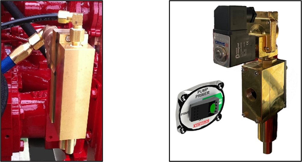
The priming system control must both activate the priming pump and open a connection between the priming pump and suction of the fire pump. This allows the vacuum produced to remove the air from the pump and hoses. Once priming is complete, and fire pump discharge pressure is established, the same control must deactivate the priming pump and close the connection between the priming pump and pump suction. Control types for priming systems include manual, automatic, and multi-location.
MANUAL CONTROLS
Manual Controls are started by the pump operator and then stopped by the operator when priming is complete and discharge pressure established. If the prime is lost at any point, the operator must restart the same priming sequence.
AUTOMATIC CONTROLS
Automatic Controls are started by the pump operator- or when the fire pump is engaged- but will stop automatically when discharge pressure is established. If the prime is lost at any point the control will automatically restart the same priming sequence.
MULTI-LOCATION CONTROLS
Multi-Location Controls are used to “pre-prime” a connected suction hose, bringing water right up to a closed gated inlet valve while operating from another water source. This allows for efficient switching from one water source to the next without getting large slugs of air into the fire pump when the gated inlet valve is opened. These additional priming locations may include front, rear, left side and right-side inlets in addition to the water pump.
Note that some industrial pumpers with water pumps larger than 2500-gpm may require more than one priming pump to remove the increased volume of air from the suction plumbing and additional large diameter suction hoses in a timely manner. Several priming system manufacturers offer dual or triplex priming pumps that operate with a single control for these applications.
Performance Testing
There are two priming system tests required by the NFPA standards. These are the “Dry Vacuum” test and the “Time-to-Water Flow” test. These tests are to be completed by the vehicle manufacturer as outlined in NFPA 1900, and on an annual basis as outlined in NFPA 1910.
The Dry Vacuum Test is run with the pump dry, and all discharges closed and capped. The primer is operated until a vacuum of 22in-Hg (for structural apparatus pumps) or 17in-Hg (for wildland apparatus pumps) is reached. The requirements are for elevations up to 2000 feet of elevation above sea level, these required vacuums can be lower by 1in-Hg for each additional 1000 feet of elevation due to the lower atmospheric pressures encountered. There is no time limit to reach this vacuum. Once the vacuum is reached, the primer is stopped, and the vacuum may not drop more than 10 in-Hg in 5 minutes. Any drop in vacuum over the limit means there are vacuum leaks in the pump or plumbing that must be fixed before running the timed water flow test.
The Time-to-Water Flow Test is usually conducted prior to the water pump performance test by the vehicle manufacturer and then annually by the Fire Department. For structural and wildland pumpers the time required to prime the dry water pump and begin to flow water must not exceed 30 seconds if the rated capacity is 1,250 gpm or less. The time to prime the dry pump and flow water must not exceed 45 seconds if the rated capacity is 1,500-gpm or more for structural pumpers. An additional 15 seconds is permitted to meet these requirements when the pump system includes an auxiliary four-inch or larger intake pipe.
Maintenance:
If the priming system fails because of poor maintenance, your water pump could be useless the next time drafting is required. Make priming system checks an integral part of your scheduled fire pump preventative maintenance and testing program. Failing to care for your priming system can lead to failure. Recommendations for each priming system vary by manufacturer. Always ask the manufacturer for specific priming system testing and maintenance information.

