Introduction
This guide is intended to provide general information for fire service personnel on the topic of HVAC (Heating, Ventilating, Air Conditioning) systems in an emergency vehicle.
There are many types of HVAC systems available commercially and custom made for apparatus manufacturers. This guide will focus on systems with a main engine driven refrigerant compressor.

Contents
Overview
HVAC is the acronym for Heating, Ventilating, and Air Conditioning, which is a system that provides heating and cooling benefits for the occupant areas of the vehicle. The primary intent of the HVAC system is to provide comfort to the occupants of the vehicle; with a focus on controlling temperature and humidity.
This guide covers a general overview of the key components of an HVAC system
- Controls
- Evaporator
- Condensate Drain System
- Condenser
- Compressor
- Receiver Dryer
Controls
HVAC temperature control can be manual or automatic. In the automatic approach, the operator sets the desired temperature value, and the system makes changes to the output to reach and maintain that temperature. In the manual system, the operator adjusts the fan speed and temperature settings independently to obtain the desired level of comfort.
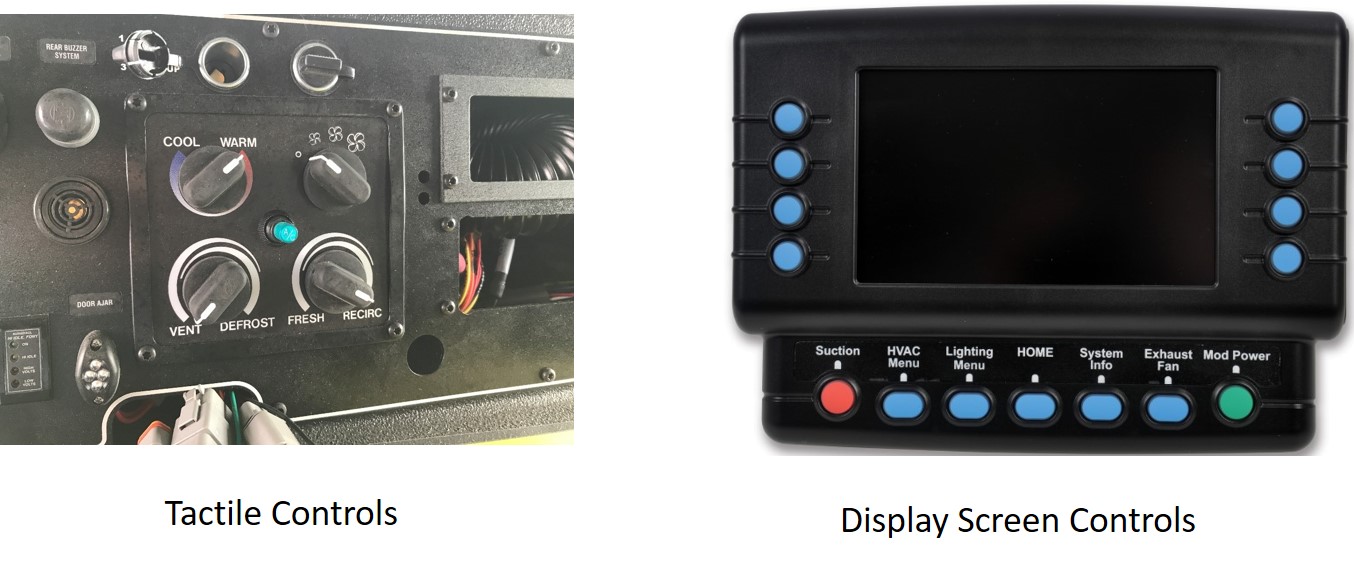
The HVAC system adjustment can be accomplished by one of two methods; tactile switches, or touchscreen displays; both accomplishing the same result. In general, the HVAC controls change the setting for: on-off power, defog/defrost/comfort air flow, blower speed, heat/cooling, and temperature.
Tactile Controls and Display Screen Controls
Tactile controls are switches or knobs that the operator must physically touch and operate (push, turn, or slide) to change the desired setting result
Pros:
- Operator can adjust without taking eyes off the road.
Cons:
- Controls consume space on the rocker switch panels which may reduce available spaces needed for other controls.
Display screen controls are typically graphical buttons on a display screen that allows the operator to change the system to the desired settings.
Pros:
- Display screen can provide richer interface with more information.
Cons:
- Multiple touch selections may be required to get to control screen.
- Requires the operator to look at the display to make adjustments.
Evaporator Coils and Heater Core
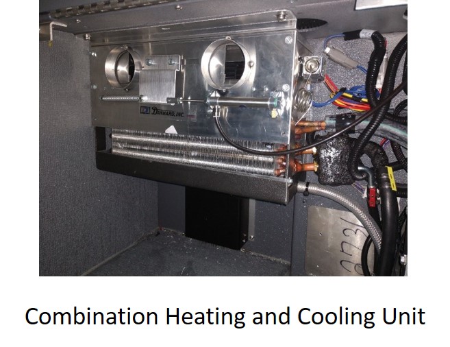
The function of the evaporator is to take high pressure liquid refrigerant and convert it to low pressure vapor. The evaporator assembly includes single or multiple blower motors. The blower motors force air from inside or outside of the cab, across the evaporator coil, reducing its temperature and forcing it out of the discharge louvers.
The function of the heater is to take the coolant of the engine, usually at a higher temperature than the ambient temperature of the occupant compartment; and circulate it through a heater coil. The blower motors force air from inside or outside of the cab across the heater coil, raising its temperature and forcing it out the discharge louvers.
The chassis designer may combine the air conditioning evaporator and heater coil in a single system, or may choose to house them in separate units.
There are four critical aspects of air flow in an HVAC system; temperature, volume, velocity, and direction.
Air temperature change is the difference between the temperature of the air going into the evaporator/heater unit (ambient) and the temperature of the air coming out of the unit. Air flow is described using two characteristics, volume and velocity. Volume, measured in cubic feet per minute (CFM), for any given temperature and pressure can determine the mass of air that is flowing. The mass of the air will determine the energy it can impart to the environment. Air velocity, which is typically measured in feet per minute (FPM), is how fast the air is flowing. Both volume and velocity are important when considering the performance of an air conditioning system.
Temperature and volume will determine the capacity of the system to effect a change in overall occupant compartment conditions. The greater the temperature difference and the higher the volume, the quicker a change can be made.
Velocity and direction are important for occupant comfort. Cooling air provides the greatest comfort when it can be directed at the occupants’ face, and they will feel cooler when that air has greater velocity. The effectiveness of a defroster also is very sensitive to the direction of the air, but velocity is less important. The key to a defroster is to direct a moderate stream of air as evenly as possible across the entire glass area being cleared.
Condensate Drain System
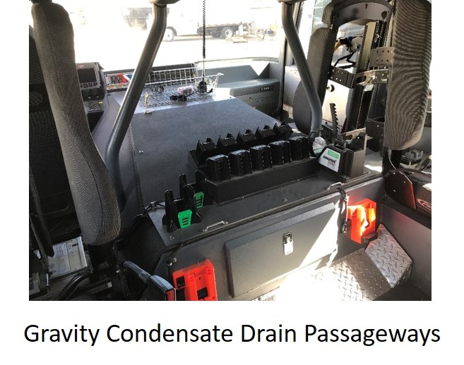
The function of the condensate drain is to dispose of the water (condensate) that comes off the evaporator coil. There are two primary methods used for extracting the condensate: gravity or the use of a pump. The drain system must be designed so it can extract condensate with the apparatus on any slope or grade that it is designed to operate.
Gravity Drain Systems and Pump Drain Systems
Gravity drain system is one where the condensate is evacuated out of the evaporator by means of drain tubes relying on gravity to drain the system condensate. When utilizing a gravity drain system it may include an anti-suction fitting in the drain tubes.
Pros:
- Power is not required to drain the condensate out of the system, allowing evacuation while the vehicle is not running.
- No serviceable electric or air pump systems to maintain.
- No noise associated with the extraction of condensate.
Cons:
- Roof-mounted evaporator drain tube passageways must drop through the cab interior.
Pump drain systems are typically accomplished using either an electric submersible pump or an air actuated siphoning system.
Pros:
- No drain tube passageways to clutter the cab interior.
Cons:
- Since this method requires power, when the vehicle is turned off the condensate is not being evacuated.
- The addition of the pumping components adds to the list of parts that may require service.
- Possibility of noise when the pump drain system turns on to extract the condensate.
Condenser
The function of the condenser is to take a high-pressure refrigerant vapor and convert it back to a high-pressure liquid that will go into the evaporator through a thermal expansion valve.
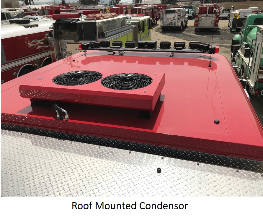
There are three common methods of condenser mounting in the emergency vehicle vocation; roof mounted, frame mounted, and cooling package mounted.
Roof Mounted Condenser, Frame Mounted Condenser and Cooling Package Mounted Condenser
Roof Mounted Condenser is mounted on the cab roof top and all the refrigerant hoses are routed through the walls or under covers inside the cab.
Pros:
- Cab roof location minimizes exposure to road grime and salt.
- No impact on engine cooling system.
- The condenser performance is not influenced by engine fan speed.
Cons:
- Electric fans increase the power load on the alternator.
- Electric fans are one more serviceable item.
- Requires protection from tree branches.
- Roof mounting creates possible leak path as sealant ages or is damaged.
Frame Mounted Condenser is mounted along the chassis frame typically under the body; refrigerant hoses are routed down along the chassis rails and the only hoses that may go into the cab are to the evaporator depending on its location.
Pros:
- Minimal visibility of the unit outside or inside the cab.
- No impact on engine cooling system.
- The condenser performance is not influenced by engine fan speed.
Cons:
- Electric fans increase the power load on the alternator.
- Electric fans are one more serviceable item.
- Susceptible to road grime and salt.
- May impact ground clearance or break-over angle.
Cooling Package Mounted Condenser is mounted in front of the engine cooling package. Cooling air is drawn through the condenser by the cooling fan or the natural passage of air during road travel.
Pros:
- No additional load on the alternator.
- No electric fans to service.
Cons:
- May decrease the performance of the engine cooling system.
- More difficult to access for service.
The sizing of the condenser needs to be such that the amount of refrigerant received from the compressor can effectively flow through the condenser coil; dissipating heat and converting the vapor to a liquid state.
Optimizing of the condenser size for the system is key to making sure performance and cost are aligned. If a condenser is undersized, the balanced system will not allow proper transition of the vapor to a liquid state, while a condenser sized too large does not increase performance as it relates to a balanced system, but does add cost.
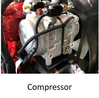
Compressor
The function of the compressor is to take a low-pressure refrigerant gas coming from the evaporator and convert it to a high-pressure refrigerant gas going into the condenser.
The compressor is one of the most important components with the HVAC system. The compressor efficiency and capacity will dictate the maximum performance of the system. The displacement per revolution measured in cubic inches (CID) along with the speed it is turning is a good indicator of the potential cooling performance of the system, assuming that the evaporator and condenser are properly sized.
It is important to understand the revolutions per minute of the compressor under normal operating conditions (idle, driving, and scene activity) to fully understand how the system will meet performance expectations. As an example, if the vehicle spends most of the time at idle, systems with higher compressor output at engine idle might be the best choice.
Receiver Drier
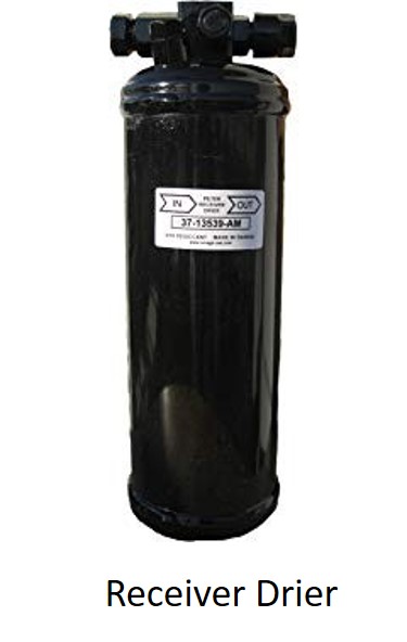
The function of the receiver drier is to keep moisture (i.e. water) out of the air conditioning refrigerant. This is accomplished by passing the refrigerant through a canister of desiccant material. Moisture in the refrigerant will cause the system to decrease in performance and may cause corrosion on internal parts. Water in the system may freeze causing more extensive damage. Receiver dryers must be replaced periodically because the desiccant can only absorb so much water. If it becomes saturated, the desiccant material can break down and contaminate the rest of the system.
System Performance vs Component Ratings
Often vehicle specifications require a system capacity stated in BTUs (British Thermal Units). Specifying system performance this way is popular because it is simple and easy to compare numbers. The problem is that there is no standard method of determining a system performance value in BTUs. The BTU rating is meaningless without knowing the test conditions it was based upon. Also, the BTU rating may be the highest individual rating of one of the system components. Either of these approaches will lead to a false comparison. A system BTU rating also ignores the other aspects of cab design that will influence comfort such as cab insulation, door sealing, window tinting, cab size, etc…
A more comparable approach is to specify conformance to a test method such as the one promulgated by the Society of Automotive Engineers SAE J2646 Cab Air-conditioning Test Procedure – Heavy Trucks, and SAE J1612 Cab Heating Systems Test Procedure and Performance Requirements – Trucks, and Multipurpose Vehicles. These test standards measure the actual performance of the entire system, and the efficiency with which the rest of the cab is designed.
Summary
In summary the HVAC system should be a balanced system to optimize the cooling/heating capabilities. Use caution when comparing systems using a stated BTU rating. A careful evaluation should be based off system performance and how it provides total comfort to the occupants of the vehicle.
Appendix - Industry Regulations and Best Practices
NFPA
None of the NFPA apparatus standards include performance aspects of HVAC systems.
- NFPA 1901Standard for Automotive Fire Apparatus
- NFPA 1906 Standard for Wildland Fire Apparatus
FMVSS
There are a few requirements contained in the Federal Motor Vehicle Safety Standards (FMVSS), but none of these specify performance.
- 49 CFR 571.101 Controls and Displays
- 49 CFR 571.103 Windshield defrosting and defogging systems
SAE
Much more comprehensive guidance can be found in the recommended practices published by the Society of Automotive Engineers.
- SAE J1487 Rating Air-Conditioner Evaporator Air Delivery and Cooling Capacities
- SAE J1612 Cab Heating Systems Test Procedure and Performance Requirements–Trucks, and Multipurpose Vehicles
- SAE J2646 Cab Air-Conditioning Test Procedure – Heavy Trucks with and without Sleepers
- SAE J2918 Engine-Off Cab Heating and Air Conditioning Systems Test Procedure and Performance Requirements – Trucks with and Without Sleepers
- SAE J381 Windshield Defrosting Systems Test Procedure and Performance Requirements–Trucks, Buses, and Multipurpose Vehicles

