TC030 Fire Apparatus Foam and Water Additive Proportioning Systems
Foam and Water Additive Proportioning Systems
Prepared by the FAMA Foam Subcommittee
This guide does not endorse any manufacturer or product

Contents
Introduction
This guide is intended to provide fire service personnel information surrounding various foam and water additive proportioning systems, sizing considerations and water additives that are commonly used in fire apparatus.
As with any engineered system design, there are advantages and disadvantages to each configuration, design and manufacturer – not all are presented in this document. It is the responsibility of the purchaser to determine what best meets their predetermined requirements and to specify this information to prospective apparatus bidders, sellers, and manufacturers.
This guide is presented as a general informative and educational piece, as technology is continuously evolving. The various options and auxiliary equipment presented may not be available from every manufacturer, and some may be mutually exclusive.
For more resources, contact the FAMA Member manufacturers listed at www.fama.org.
The National Fire Protection Association (NFPA) Standards define voluntary minimum standards for automotive fire apparatus and water additives.
The following are widely used:
- NFPA 1901, Standard for Automotive Fire Apparatus
- NFPA 1906, Standard for Wildland Fire Apparatus
- NFPA 11, Standard for Low, Medium and High Expansion Foam
- NFPA 18, Standard on Wetting Agents
- NFPA 1150, Standard on Foam Chemicals for Fires in Class A Fuels
It is recommended to reference current NFPA edition when specifying new apparatus.
Overview
Proportioning in fire apparatus applications is simply creating a solution by adding concentrate or a water additive. Proportioning systems to accomplish this are available in a wide range of performance, features, and cost; and there is no one system on the market that will accomplish everything. As a first step, it’s important to carefully and realistically identify needs based on hazards in your coverage area. Equally critical is understanding the water additives available, their functions, applications and mixture requirements. This information will assist with evaluation and proper selection of a proportioning system to meet expectations.
This paper will cover the following in general terms:
- Hazard Evaluation
- Water Additives
- Sizing a System
- Selecting Proportioning Systems
- Design the Apparatus
Hazard Evaluation
As a first step, identify the hazards you may encounter with the apparatus. Are your department’s primary responsibilities residential, wildland, marine or industrial areas? Or perhaps a combination such as rail or trucks carrying fuels that travel through a municipal department’s coverage?
Identify the types of fuel that are associated with these hazards; Class A, Class B, other? What are the potential fuel loads and flow rates to extinguish? The goal is to determine the maximum expected water flow rate to be treated. To assist with this evaluation, understand recommended critical application rates required for the hazard and potential fuel load. In addition to your experience, some good tools and resources for direct attack critical application rate guidance include; The Iowa Formula or National Fire Academy that both provide a formula to estimate flow requirements for three dimensional Class A type fires; each with their own caveats. For Class B hazards, NFPA 11 and the concentrate manufacturer are excellent resources for these two-dimensional hazards.
In addition to determining maximum flow requirements, minimum flow of water to be treated should also be identified. Do you plan to use solution during mop-up or other low flow applications?
Water Additives
Before evaluating proportioning systems, it is important to plan for the appropriate water additive. It is important for the purchaser to understand the types and properties of mechanical water additives and its application to specify a proportioner properly.
There are numerous types and brands available; all designed for various applications. To choose the correct proportioner and size, one must know the mixture of the solution (minimum and maximum), corrosive properties and viscosity. The following is a brief synopsis covering more common types and solution ratios in use today:
- Class A Foam – A surfactant used on Class A type fire applications that reduces surface tension of water making it more effective at wetting. The solution is normally dictated by the use at the following general rates:
- 0.3% Mop-Up
- 0.5% Initial Attack
- 1% Exposure Protection
- Class B Foam – used on two-dimensional hydrocarbon or polar solvent type fires and designed to extinguish by creating a blanket or film over the fuel. Unlike Class A, the mixture of the solution is dictated by the foam concentrate manufacturer based on the fuel type and application.
- Class B foam engineered for hydrocarbon fires is usually applied at 1%, 3% or 6%.
- Class B foam engineered for polar solvents is usually applied at 3% or 6% and typically has prefix of “AR” for Alcohol Resistance in the description.
- Class B Multi-Use foam is engineered for both hydrocarbon and polar solvent. The product is marked with two percentage rates commonly 1% x 3%, 3% x 3% or 3% x 6%. The first number indicates use on hydrocarbon and the second polar solvent type fires.
- Emulsifiers, wetting agents and gels – used for many different applications and the recommended solution varies based on manufacturer and application.
Sizing the System
The next step is determining the size of proportioning system. With so many proportioning systems to choose from, how do you determine which one is right for you? After defining the hazards and flow requirements, it is important to understand the capabilities and limitations of each system.
The following few basic questions will quickly narrow down the list:
- What water additives previously discussed are to be used?
- Will it just be one or several?
- The proportioner you choose must be compatible with the concentrate(s) and may require flushing capabilities.
- How accurate do you want your system to be?
- NFPA 1901 & 1906 are minimum standards. There are other considerations related to accuracy: The logistical impact in supplying extra foam to the system in fire ground operations, the cost associated with consuming extra amounts as well as possible environmental impacts. Know the accuracy capability of the systems and calculate the cost of wasted foam; based on how much solution you can expect to flow.
- What is the viscosity of the concentrate(s) you plan to use?
- Clarify how the concentrate manufacturer measures the viscosity and how the proportioner manufacturer rates the system. Make sure both are using the same test standard and the proportioner is compatible with the concentrate.
- What proportioning rate(s) are required?
- Class B foam may only require a single rate such as 3%. Class A foam may require 0.3% to 1.0%; dependent on use. If you are using both Class A and B concentrates, the proportioner capacity range will broaden. Some proportioning technologies can provide this wider performance while others may be challenged.
- How many solution capable discharges are required?
- Identify each discharge and size
- How many will be in service at any given time (Minimum and maximum flow)?
- What are their flow rates? Determine what minimum and maximum solution flow rates will be. Will the system you are considering, handle these?
- Will the solution percentage out of each discharge always be the same or does each require the capability to adjust percentage or flow plain water?
- What operating pressures will be encountered? (Minimum and maximum for both discharge and intake).
- Some systems will not operate effectively with pressure on the intake side while others are not affected.
- Some systems have the capability to proportion on both normal and high pressure discharges.
- How long will your hose lays be and how high will your nozzle be elevated (uphill, high rise or aerial operations)?
- Determine if these or other operating conditions will affect the performance of the proportioner.
- What is longest estimated duration of the attack?
- How much foam concentrate will you require?
- Where will it come from – an onboard tank, an off-board pickup, or both?
- Do you require the ability to calibrate the system to the viscosity of the concentrate(s) you will be using?
- Do you require the ability to periodically test the system for readiness?
These items are key to successfully determining size and technology of proportioner to utilize. Most proportioning manufacturer’s will publish the amount of water their equipment is capable of treating and associated percentages for initial guidance.
Selecting Proportioning Systems
While there are a wide variety of systems and models offered, most are based on relatively few technologies, or some variation of one of these basic technologies. It is important to understand operation characteristics along with features and benefits so that the system chosen meets the requirements. Each will have minimum and maximum capacities providing a variety of water flow ranges that can be treated at given percentages. The information gathered previously will provide general guidance on capacity sizing.
As an example:
- Class A foam
- Maximum water flow to be treated: 500 GPM
- Maximum solution rate: 1%
- Maximum system capacity: 500 GPM x 1% = 5 GPM
- Minimum water flow to be treated: 40 GPM
- Minimum solution rate: 0.5%
- Minimum system capacity: 40 GPM x 0.5% = 0.2 GPM
In this scenario, the system must have a capacity range of 0.2 to 5 GPM. Understanding the capacity range of the proportioning system or device and making sure it meets expectations is required.
In most cases there are several competitors operating in each category listed above. Following are some generalities regarding each of the categories:
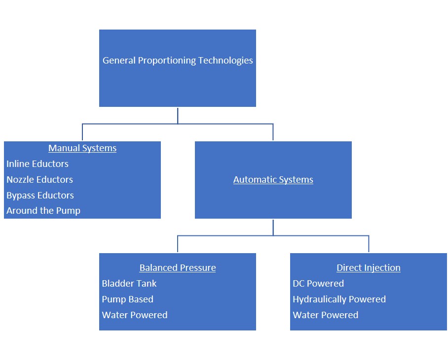
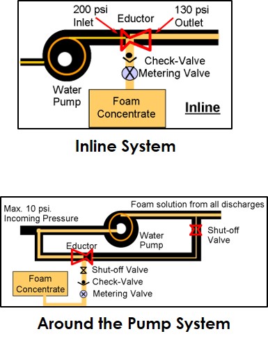
MANUAL SYSTEMS
Manual systems are generally eductor based. Some are designed to be installed in the apparatus plumbing while others can be used in the fire line. Fire pump discharge water is forced through the eductor venturi creating a vacuum. This causes foam concentrate to be pushed into the eductor by atmospheric pressure. Solution rates are adjusted manually to variations in flow. Around the Pump systems route a small amount of discharge through the venturi and return the foam solution to the fire pump suction. Note that there are some Around the Pump systems designed to adjust automatically by utilizing flowmeters and electronic controls.
Types of Manual Systems:
- Inline Eductors
- Nozzle Eductors
- Bypass Eductors
- Around the Pump
General characteristics of manual systems:
- Narrower performance range
- Lowest system and installation cost
- Operating cost varies
- Accuracy varies
- Some have pressure loss
- Single-point injection
- On-board / Off-board foam pickup capability varies
Manual system limitations
- Inlet pressures
- Hose lay length
- Nozzle elevation
- All discharges are solution with Around the Pump systems
AUTOMATIC SYSTEMS
Automatic systems are typically engineered into the apparatus plumbing and designed to maintain solution rates automatically based on water flow variations. The operator sets a solution rate and the system will adjust to meet the concentrate requirements. There are a number of technologies utilized to accomplish the proportioning with most falling under mechanical or electronic/computer control.
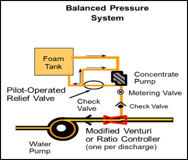
BALANCE PRESSURE SYSTEMS
Balance pressure systems are installed on the discharge side of the water pump. The concentrate is moved to the discharge by a pump, bladder or water power. Two orifices discharge water and foam concentrate into a common ratio controller located in the discharge. The system balances the pressures of each. Those utilizing a concentrate pump are designed to either by-pass excess foam via a recirculation line or control the concentrate pump speed on per demand. The concentrate pumps are typically driven via electric motor or hydraulics.
General characteristics include:
- Medium performance range
- Higher system and installation cost
- Operating cost varies
- Accuracy varies
- Some have pressure loss
- Single or multiple injection point
- On-board / Off-board foam pickup capability varies
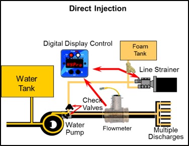
DIRECT INJECTION- FLOW BASED
Direct injection systems use a concentrate pump to inject directly into the water pump discharge. The systems utilize flow sensing devices, computers and electronic controls to automatically compensate for flow requirements. The concentrate pumps are driven via electric motor or hydraulics.
General characteristics include:
- Wide performance range
- Higher system and installation cost
- High accuracy
- Lower operating cost
- No discharge pressure loss
- Single or multiple injection point – varies
- On-board / Off-board foam pickup capability varies
- Not affected by incoming fire pump pressure
Designing the Apparatus
Foam systems designed to be incorporated into the apparatus are designed and installed by a certified fire apparatus OEM, dealer or service facility. The information gathered above will provide guidance to discuss with the installer so that the system chosen meets expectations. The following are additional system related items to discuss and clarify with your installer (reference NFPA 1901 and NFPA 1906 chapter 20):
- To determine concentrate cell(s) size, what is anticipated duration of attack and how much foam concentrate will be required? (Maximum expected water flow x maximum solution rate percentage x time)
- Where will the concentrate be stored? On-Board cell(s) or off-board pickup? Is more than one concentrate required?
- Which specific discharges are foam capable and define location.
- Does the system require flushing and how is it accomplished?
- Is the proportioning system electrically powered and if so, what are the requirements?
- Are there special plumbing and associated material requirements?
- What items need access for repair, service or maintenance and where will they be located?
In addition, proportioner manufacturers offer numerous application specific options and accessories; Manual & electronic dual tank valves, auto-on capabilities, dual & multi-point injection, remote start-stop and off-board pick-up. If the foam cell(s) are mounted on the apparatus, a refill system allowing replenishment from the ground is highly recommended. This will keep personnel off of the top of the apparatus where the foam cell access is typically located.
Once you have taken delivery of the apparatus, make sure you fully understand the operation and maintenance requirements of the system. Basing your decision on the information gathered above and discussed with your installer will assure your proportioning expectations are met. Verify that the system has been properly installed and calibrated per the foam equipment manufacturer’s performance specification and has been tested to the points defined in NFPA 1901 and NFPA 1906 chapter 20.
